───✱*.。:。✱*.:。✧*.。✰*.:。✧*.。:。*.。✱ ───
Introduction
- Skynet Healthcare is a fast-growing insurer that uses data analytics and predictive health modeling to manage customer policies and claims. In this scenario, Customer Service Representative Sarah Connor, working at the LA regional office over the
SKYNET_SECUREWi-Fi, uses a web-based Customer Management Portal to look up John Connor’s policy (ID:T-800-2029). Analyzing this single lookup through the OSI model clarifies how each network layer contributes to security, reliability, and performance as the request traverses the Regional Office, Corporate WAN, and Data Center—and hoow those layers interoperate to deliver actionable information to the browser.
Network Topology
Diagram
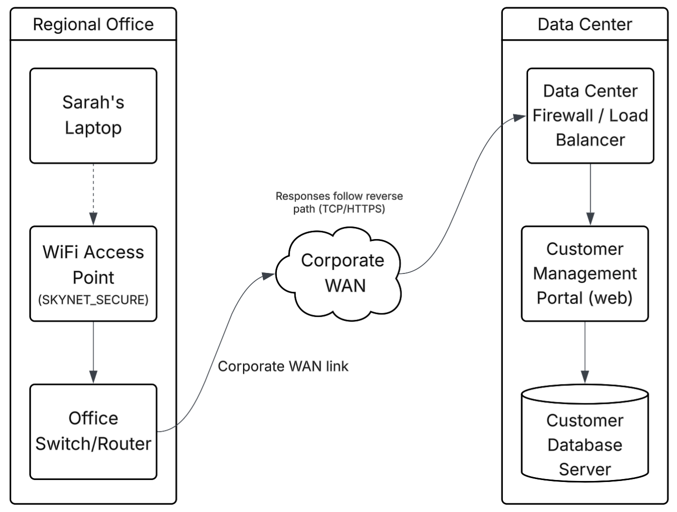
Legend
- Dashed Line → WiFi
- Solid Line → Wired connection
Connection Explanation
- Regional Office → Sarah’s Laptop connects over the
SKYNET_SECUREWi-Fi to the access point, which uplinks to the office switch/router (default gateway). - Corporate WAN → the office switch/router forwards traffic into the corporate WAN toward the data center.
- Data center → traffic enters the data center firewall/load balancer, which forwards requests to the customer management portal (web tier). The portal queries the database server and returns results the same path in reverse.
Topology Type
- Site LAN → star topology (devices connect to a WiFi AP/switch that uplinks to the site gateway)
- Corporate WAN → hierarchical, partial-mesh routed WAN (sites hub to a provider/core, centralized data center services)
- Data Center → multi-tier architecture; perimeter firewall/load balancer → customer management portal (web application) → backend database server
OSI Layer Analysis
Request Analysis (Laptop → Server)
Layer 7 - Application
- Sarah enters
T-800-2029in the Customer Management Portal and clicks SEARCH. - The browser prepares an HTTP request (GET/POST) to the portal’s search endpoint and includes authentication state (with cookies or JWT)
Layer 6 - Presentation
- The browser negotiates TLS (HTTPS), encodes the HTTP message (UTF‑8), and encrypts it using the negotiated ciphers and keys.
- Optional parameters such as ALPN (e.g., h2) and compression are set if negotiated; cookies and payload are protected on the wire.
Layer 5 - Session
- A secure TLS session is established or resumed with the portal VIP. HTTP keep‑alive allows multiple requests over the same connection.
- Session identifiers bind Sarah’s authenticated browser session to server‑side state.
Layer 4 - Transport
- TCP performs the three‑way handshake, segments the encrypted payload, numbers segments, and uses ACKs/retransmissions for reliability.
- Flow control (windowing) and congestion control (e.g., CUBIC/BBR) adapt to WAN conditions.
Layer 3 - Network
- The laptop sources an IP packet to the portal VIP and forwards it to the default gateway (Office Switch/Router).
- Enterprise routing carries the packet across the Corporate WAN to the data center; NAT may translate the private source at the site edge.
Layer 2 - Data Link
- Laptop ↔ AP: IEEE 802.11 frames over
SKYNET_SECURE(WPA2/WPA3) carry the packet. - AP ↔ switch/router and onward: Ethernet (802.3) frames forward based on MAC addresses; VLANs may segment wireless traffic.
Layer 1 - Physical
- RF on 2.4/5/6 GHz transports bits between the laptop and AP.
- Copper/fiber links carry signals from AP → switch/router → WAN → data center cabling.
Response Analysis (Server → Laptop)
Layer 1 - Physical
- Electrical/optical signals traverse data center cabling, WAN fiber/copper, office cabling, and RF from the AP back to the laptop.
Layer 2 - Frame Handling
- Ethernet frames switch across the data center and site networks; WAN encapsulations (e.g., MPLS) are removed at the edge.
- The AP encapsulates downlink traffic into 802.11 frames for delivery to the laptop.
Layer 3 - Return Routing
- IP routing delivers packets from the portal/load balancer back to the client’s address (or translated address), using existing state in NAT/firewall tables.
Layer 4 - Data Reassembly
- TCP reorders segments, acknowledges receipt, and triggers retransmissions as needed, delivering a reliable byte stream to the browser.
Layer 5 - Session Maintenance
- The same TLS session remains active; keep‑alive and session resumption reduce overhead for subsequent requests.
Layer 6 - Data Formatting
- The browser decrypts TLS and parses the HTTP response (HTML/CSS/JS and/or JSON). If compression (gzip/br) was negotiated, it is decompressed and decoded (UTF‑8).
Layer 7 - Application Display
- The portal renders John Connor’s policy details (coverage status, plan, dates) in the browser UI. Client‑side scripts may issue additional HTTPS requests over the same session to populate related fields.
Conclusion
- This lookup shows how all seven OSI layers work together: the app shapes the request, TLS (presentation/session) secures it, TCP delivers it reliably, IP routes it across the WAN, Ethernet/Wi‑Fi frame it locally, and the physical layer carries the bits.
- I learned that Wi‑Fi encryption and end‑to‑end TLS solve different problems, that NAT/firewalls/load balancers affect flows at specific layers, and that mapping symptoms to layers is the fastest path to troubleshooting. Overall, the OSI model gave me a clear, practical way to reason about secure, reliable enterprise communication.
───✱*.。:。✱*.:。✧*.。✰*.:。✧*.。:。*.。✱ ───