───✱*.。:。✱*.:。✧*.。✰*.:。✧*.。:。*.。✱ ───
Network Overview
Screenshot
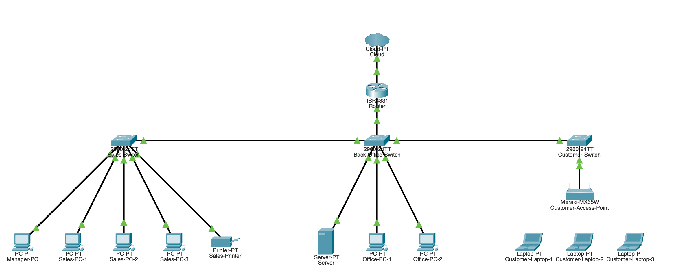
Topology
- The topology chosen is a star mesh, since it was the easiest to implement and it makes the most sense for the given network. I chose this topology because it provides an easy way to encapsulate the different VLANs, whereas with something like a mesh network, it can get a litlte messy.
- This topology is appropriate for a retail store because you have different segregated parts of the network, and the star topology makes this easy to manage.
Hardware and Cabling
Devices Used
- Router → ISR4431
- Switches → 2960 IOS15
- PCs → PC-PT
- Printers → Printer-PT
- Laptops → Laptop-PT
- Servers → Server-PT
Switch Placement
- Each switch is for their own section essentially. The main limitation behind this setup was the router not having 3 ethernet ports that were able to be configured for the VLANs, so I had to set up the back office switch as a “core switch” that connected to the guest and the sales VLANs.
- This was accomplished by setting the port that connected to the router as a “trunk” and then configuring the VLANs inside the witch and the ip addresses from the router, which ended up working.
Cables
- For every cable, I used copper straight-through. I had no need for other cables, as I’m not using any serial ports or anything.
OSI Model Questions
- Your switches operate at which OSI layer? Explain what happens at this layer when Sales-PC1 sends data to Sales-PC2
- The switches operate in OSI layer 2 (data link). Whenever Sales-PC1 sends data to Sales-PC2, Sales-PC1 ARPs to learn Sales-PC2’s MAC address, the switch floods the ARP request within VLAN 10, learns MAC to port mappings, and then forwards the unicast frames based on the destination MAC only to Sales-PC2’s port (no router involved as 802.1Q tags are carried only on trunk links)
───✱*.。:。✱*.:。✧*.。✰*.:。✧*.。:。*.。✱ ───